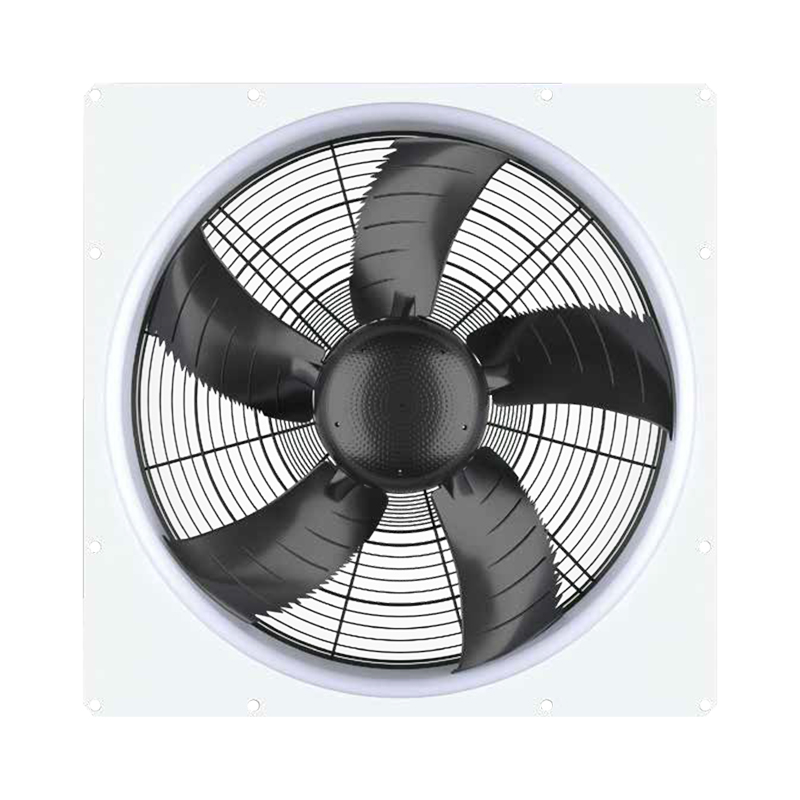
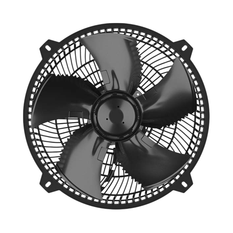
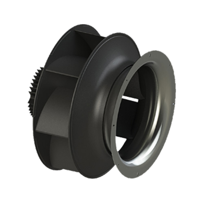
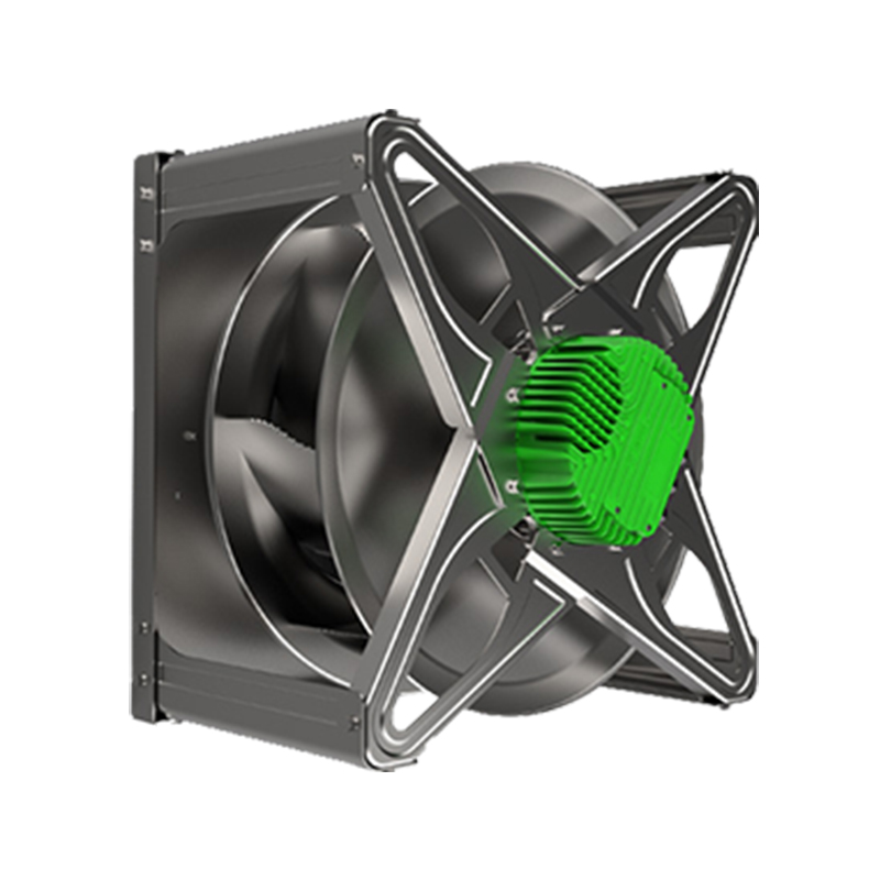
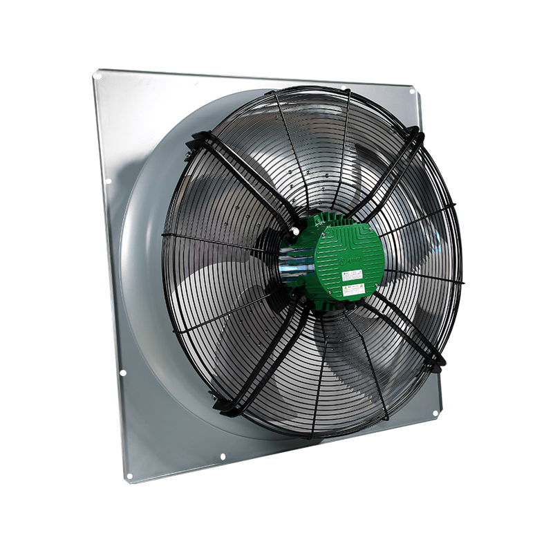
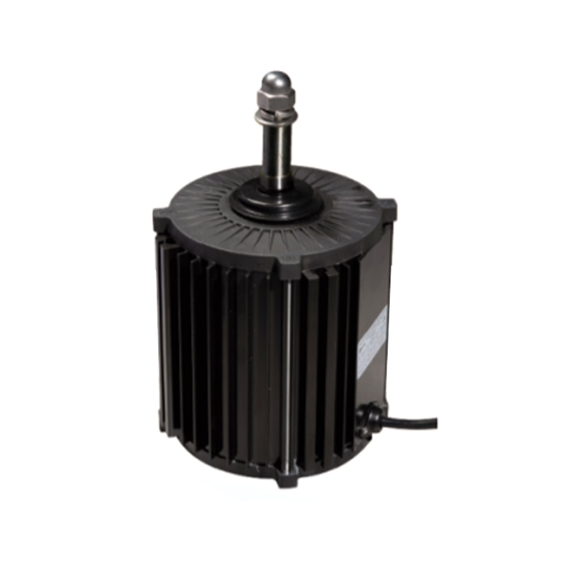
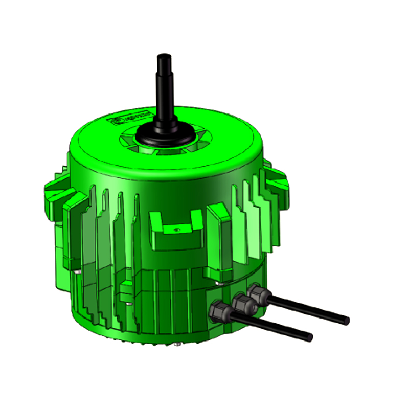
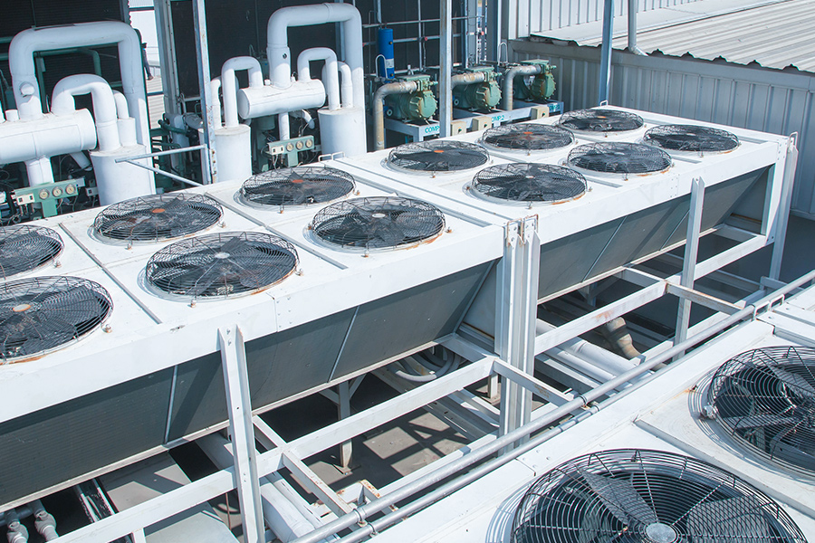
The three primary types of fan motors are AC Fan Motors, DC Fan Motors, and EC Fan Motors. AC fan motors run directly on alternating current from the grid and are the most widely installed type in industrial and commercial HVAC equipment. DC fan motors operate on direct current, offering precise speed control and high efficiency at low to medium power ratings. EC fan motors (electronically commutated) combine a DC permanent magnet motor with an integrated inverter, delivering the speed flexibility of DC technology with the ability to connect directly to an AC supply, achieving efficiencies of 75 to 90% that neither standard AC nor basic DC motors can match at comparable power levels. Within these three categories, the most important subtypes for industrial and commercial applications are the three-phase asynchronous fan motor, brushless axial fan motors, and Axial Fan Motors more broadly. Choosing the wrong motor type for a ventilation, refrigeration, or HVAC system leads to excess energy consumption, premature failure, control incompatibility, and regulatory non-compliance. This guide provides the technical depth needed to choose correctly.
What Are the Three Types of Fan Motors? A Direct Answer
The three types of fan motors that define the modern fan motor market are classified by their power supply and commutation method:
- AC Fan Motors: Powered by alternating current (single-phase at 100 to 240 V or three-phase at 200 to 480 V), using induction or synchronous operating principles. The dominant technology in installed commercial and industrial fans worldwide due to low unit cost and compatibility with standard grid supply.
- DC Fan Motors: Powered by direct current (typically 5 V to 48 V for electronics cooling; 12 V to 310 V for larger applications), using brushed or brushless commutation. Most modern DC fan motors are brushless for longer service life and higher efficiency. Common in electronics, telecommunications, automotive, and battery-powered applications.
- EC Fan Motors: Electronically commutated motors that accept AC supply input and convert it internally to DC via a rectifier and inverter circuit, driving a permanent magnet DC motor. EC motors combine AC supply compatibility with DC motor efficiency and electronic speed control. Efficiency ratings of 75 to 90% make EC the preferred choice for energy-regulated HVAC, refrigeration, and ventilation applications.
These three categories are sometimes further divided by airflow orientation (axial, centrifugal, mixed flow) and by construction (single-phase shaded pole, capacitor-run, three-phase induction, permanent magnet synchronous). The following sections cover each type in full practical detail.
The three fan motor types compared by power supply, typical efficiency, speed control method, and primary application
| Motor Type |
Power Supply |
Typical Efficiency |
Speed Control |
Primary Application |
| AC Fan Motors |
AC 100 to 480 V |
50 to 75% |
Fixed speed or VFD |
Industrial HVAC, commercial cooling |
| DC Fan Motors |
DC 5 to 310 V |
60 to 85% |
PWM, voltage control |
Electronics, telecom, automotive |
| EC Fan Motors |
AC 100 to 277 V |
75 to 90% |
Integrated electronics, 0 to 10 V, PWM |
Energy-regulated HVAC, refrigeration |
AC Fan Motors: How They Work, Major Subtypes, and Where They Excel
AC Fan Motors operate on the principle of electromagnetic induction. An alternating current flowing through the stator windings creates a rotating magnetic field, which induces a current in the rotor and generates the torque that rotates the shaft. The rotor speed lags slightly behind the rotating magnetic field — this lag is called slip, and it is what defines induction (asynchronous) motor operation. AC fan motors require no brushes, commutators, or internal electronics in their basic form, which makes them inherently robust and low maintenance.
Single-Phase AC Fan Motors: Shaded Pole and Capacitor Types
Single-phase AC fan motors are used in residential HVAC, small commercial units, and appliances where only a single-phase supply is available. The two main subtypes are:
- Shaded-pole motors: The simplest and lowest-cost AC fan motor, using a short-circuited copper ring (shading coil) on part of each stator pole to create a phase-shifted magnetic field that initiates rotation. Efficiencies are very low, typically 15 to 35%, and power output is limited to approximately 1 to 50 W. Used in small domestic fans, refrigerator evaporator fans, and microwave turntable motors where low cost and very low power needs dominate. Their low efficiency makes them increasingly unsuitable for products subject to energy efficiency regulations such as EU ErP Directive targets.
- Capacitor-run motors (permanent split capacitor, PSC): Use a run capacitor in series with an auxiliary winding to create a two-phase rotating field in a single-phase supply. Significantly more efficient than shaded-pole motors, typically 50 to 65%, and available in outputs from 25 W to 2 kW. Standard in residential air conditioner fan motors, furnace blowers, and commercial refrigeration condenser fans. The capacitor is the most common failure point in PSC motors and should be checked first when diagnosing a non-starting fan motor.
Three-Phase Asynchronous Fan Motor: The Industrial Standard
The three-phase asynchronous fan motor is the workhorse of industrial ventilation, commercial HVAC, and large cooling tower systems. Powered by three-phase AC supply (typically 380 to 480 V at 50 or 60 Hz), these motors produce a naturally balanced rotating magnetic field from the three-phase current without requiring capacitors or starting windings.
Key characteristics of three-phase asynchronous fan motors:
- Synchronous speed is determined by the supply frequency and the number of motor poles: synchronous speed (RPM) = (120 × frequency) / number of poles. A four-pole motor on a 50 Hz supply runs at a synchronous speed of 1,500 RPM; actual speed under load is approximately 1,420 to 1,470 RPM due to slip.
- Efficiency: Three-phase induction motors in industrial sizes (1.1 kW and above) achieve efficiencies of 85 to 95% at full load, well above single-phase types. IE3 (Premium Efficiency) rated three-phase motors are mandated in many markets for motors above 0.75 kW under IEC 60034-30-1 and equivalent regulations.
- Power range: Three-phase asynchronous fan motors are available from approximately 0.06 kW to over 500 kW, covering everything from small exhaust fans to large industrial process fans and cooling tower fans.
- Starting torque and inrush current: Direct-on-line (DOL) starting of three-phase induction motors generates an inrush current of 5 to 8 times the full-load current, which can cause voltage dips on weak grids and mechanical stress on fan impellers. Star-delta starters, soft starters, and variable frequency drives (VFDs) are used to limit inrush current and protect both the motor and the electrical supply.
- Speed control with VFD: Pairing a three-phase asynchronous fan motor with a variable frequency drive allows continuous speed control from near-zero to full speed. Since fan power consumption follows the cube law of affinity (reducing fan speed to 80% reduces power to approximately 51% of full-load power), VFD control offers enormous energy savings in applications with variable airflow requirements.
AC Fan Motor Speed and Pole Count Reference
Synchronous and approximate full-load speeds for three-phase asynchronous fan motors at 50 Hz and 60 Hz supply
| Number of Poles |
Synchronous Speed (50 Hz) |
Full Load Speed (50 Hz) |
Synchronous Speed (60 Hz) |
Full Load Speed (60 Hz) |
| 2 poles |
3,000 RPM |
2,850 to 2,900 RPM |
3,600 RPM |
3,450 to 3,480 RPM |
| 4 poles |
1,500 RPM |
1,420 to 1,470 RPM |
1,800 RPM |
1,725 to 1,750 RPM |
| 6 poles |
1,000 RPM |
940 to 960 RPM |
1,200 RPM |
1,140 to 1,160 RPM |
| 8 poles |
750 RPM |
700 to 730 RPM |
900 RPM |
850 to 870 RPM |
When to Choose AC Fan Motors
- Fixed-speed applications where airflow requirements do not change and continuous variable control is not needed, such as constant-volume duct exhaust systems
- High-power industrial fans (above 5.5 kW) where three-phase induction motors with IE3 efficiency rating represent the most cost-effective and proven technology
- Harsh environments where a simple, robust induction motor with no internal electronics is more reliable than an EC motor with integrated control circuitry subject to voltage transients, moisture, or high temperature
- Budget-constrained projects where upfront equipment cost is the primary driver and variable speed control is achievable through an externally mounted VFD
DC Fan Motors: Operation, Brushless Technology, and Precision Speed Control
DC Fan Motors operate by passing direct current through windings that interact with a permanent magnetic field to produce rotational torque. In brushed DC motors, current commutation (switching current direction in the windings as the rotor turns) is performed mechanically by carbon brushes contacting a copper commutator. In brushless DC (BLDC) motors, commutation is performed electronically by sensing rotor position and switching current in the stator windings accordingly, eliminating all mechanical wear from the commutation process.
Brushed vs. Brushless DC Fan Motors: Why Brushless Has Become the Standard
Brushed DC fan motors were the dominant type in electronics cooling through the 1980s and 1990s but have been almost entirely replaced by brushless types in new designs. The reasons are decisive:
- Service life: Brush wear limits brushed DC motors to service lives of approximately 1,000 to 3,000 hours before brush replacement is needed. Brushless DC fan motors operate for 30,000 to 70,000 hours or more, limited primarily by bearing life rather than any wearing contact. This difference is critical in data centers, telecommunications racks, and industrial process equipment where unplanned maintenance is unacceptable.
- Efficiency: Brushless DC motors eliminate the resistive losses and friction losses associated with brush contact, improving efficiency by typically 5 to 15 percentage points over equivalent brushed designs. A brushless DC fan motor in the 10 to 100 W range typically achieves efficiencies of 65 to 85%.
- EMI (electromagnetic interference): Brush arcing in brushed motors generates significant electromagnetic interference that can disrupt sensitive electronics in the same system. Brushless motors produce no brush arcing and are far more compatible with sensitive electronic environments.
- Speed control: Brushless DC motors respond rapidly to pulse-width modulation (PWM) speed control signals, enabling precise, quiet speed adjustment from near-zero to maximum speed. PWM control at frequencies of 25 kHz or higher is above the audible range, eliminating the coil whine that lower PWM frequencies produce in some applications.
PWM Speed Control for DC Fan Motors: How It Works
Pulse-width modulation (PWM) controls a DC fan motor's speed by rapidly switching the supply voltage on and off at a fixed frequency, varying the proportion of time the voltage is applied (the duty cycle). A duty cycle of 100% means full voltage applied continuously (maximum speed); a duty cycle of 50% means voltage applied half the time (approximately half maximum speed). The motor responds to the average voltage represented by the duty cycle. Key PWM parameters:
- PWM frequency: The Intel 4-wire PWM fan standard specifies a PWM frequency of 25 kHz for computer cooling fans. Industrial brushless DC fans may use frequencies from 1 kHz to 100 kHz depending on the control electronics.
- Minimum duty cycle: Most brushless DC fan motors have a minimum duty cycle below which they will stall rather than spin slowly. Typical minimum reliable operating duty cycle is 20 to 30%, below which the motor lacks sufficient torque to maintain rotation against bearing friction and fan blade aerodynamic resistance.
- Speed feedback (tachometer signal): Premium brushless DC fan motors provide a tachometer (tach) output signal, typically a square wave pulsing at 2 pulses per revolution, allowing the control system to verify actual fan speed and detect fan failure. This is standard in server and data center cooling applications where fan failure monitoring is critical.
DC Fan Motor Supply Voltages and Application Ranges
DC fan motor supply voltage ranges with typical power output and primary application sectors
| Supply Voltage |
Typical Power Range |
Primary Application |
| 5 V DC |
0.5 to 3 W |
USB-powered devices, small electronics |
| 12 V DC |
1 to 30 W |
PC cooling, automotive, small HVAC |
| 24 V DC |
5 to 100 W |
Telecom racks, industrial panels, HVAC |
| 48 V DC |
20 to 300 W |
Data centers, telecom, battery systems |
| 310 V DC |
100 to 1,500 W |
EC motor internal bus, large brushless fans |
EC Fan Motors: The Efficiency Standard for Modern HVAC and Refrigeration
EC Fan Motors (electronically commutated motors) are the fastest-growing fan motor category in commercial HVAC, refrigeration, and ventilation, driven by increasingly stringent energy efficiency regulations and the measurable operating cost savings they deliver over the lifetimes of installed systems.
How EC Fan Motors Work: AC Input, DC Operation
An EC fan motor accepts standard AC supply voltage (typically 100 to 240 V AC single-phase or 200 to 480 V AC three-phase) at its input terminals and converts it internally through the following stages:
- Rectification: An internal bridge rectifier converts the AC input to a DC bus voltage, typically approximately 310 V DC from a 220 V AC input (peak AC voltage).
- Power factor correction (PFC): Premium EC motors include an active PFC stage that ensures the motor draws current from the supply in phase with the voltage, achieving power factors of 0.95 to 0.99. This reduces reactive power loading on the electrical supply and avoids power factor penalties from utilities.
- Inverter stage: The DC bus voltage is converted back to a variable-frequency, variable-amplitude AC waveform by an IGBT (insulated gate bipolar transistor) inverter. This waveform drives the permanent magnet rotor of the motor at precisely controlled speed and torque.
- Electronic commutation: Hall-effect sensors or sensorless back-EMF detection determine rotor position and control the inverter switching sequence to maintain optimal torque angle between the stator field and the permanent magnet rotor at all times.
The result of this architecture is that EC motors achieve overall system efficiencies of 75 to 90% across a wide speed range, compared to 50 to 70% for typical AC induction fan motors at full load and significantly lower at partial loads where induction motors are least efficient.
EC Motor Efficiency at Part Load: The Critical Advantage
The most compelling advantage of EC fan motors over AC induction motors is their ability to maintain high efficiency across a wide speed and load range. Most commercial HVAC fans operate at part load for the majority of their running hours. A standard AC induction fan motor running at 60% of full speed via a voltage-reducing speed controller (typical in older installations) loses 30 to 50% of its efficiency compared to full-speed operation. An EC motor at the same 60% speed retains 85 to 90% of its full-speed efficiency, because the electronic commutation continuously optimizes the motor's operating point regardless of speed.
A practical energy comparison for a typical 250 W fan running at 70% average load for 8,000 hours per year:
- AC PSC motor at 70% load: Efficiency drops to approximately 45%. Energy consumption: (250 W × 0.70 load) / 0.45 efficiency × 8,000 hours = approximately 3,111 kWh per year.
- EC motor at 70% load: Efficiency remains approximately 80%. Energy consumption: (250 W × 0.70 load) / 0.80 efficiency × 8,000 hours = approximately 1,750 kWh per year.
- Annual energy saving per motor: approximately 1,361 kWh, which at a commercial electricity rate of $0.15 per kWh represents a saving of approximately $204 per motor per year.
EC Motor Control Interfaces: 0 to 10 V, PWM, and Building Automation Systems
EC fan motors include integrated control electronics that accept speed command signals from external controllers, building management systems (BMS), or thermostatic controllers. Standard control interfaces include:
- 0 to 10 V analog signal: The most widely used control interface for EC fans in commercial HVAC. A 0 V signal commands the minimum speed (or motor off); a 10 V signal commands maximum speed. Linear interpolation between these points provides continuous proportional control.
- PWM signal (0 to 100% duty cycle): Used where a building controller or variable air volume (VAV) box controller provides a PWM speed command output. The EC motor's internal electronics convert the duty cycle directly to a speed setpoint.
- RS-485 serial bus with Modbus or BACnet protocol: Premium EC motors include digital communication ports allowing integration into full building automation systems, enabling remote monitoring of motor speed, power consumption, operating hours, and alarm conditions from a central BMS.
- Onboard potentiometer: Most EC fans include a manual speed adjustment potentiometer accessible after installation, useful for setting a fixed operating speed without an external controller.
EC Motor Regulatory Compliance: ErP, IE5, and Energy Efficiency Directives
Energy efficiency regulations are the primary driver of EC motor adoption in commercial and industrial fan applications. Key regulatory frameworks:
- EU ErP Directive (Energy-related Products): Regulation EU 327/2011 sets minimum efficiency levels for fans from 125 W to 500 kW. The most recent tiers effectively mandate EC or VFD-controlled AC motors for most commercial fan applications, as standard fixed-speed AC induction fan motors cannot meet the required efficiency grades.
- IE5 (Ultra Premium Efficiency): The IEC 60034-30-1 standard defines motor efficiency classes IE1 through IE4, with IE5 (sometimes called Ultra Premium or Super Premium) representing the highest tier. EC permanent magnet motors typically fall into the IE4 to IE5 range, while standard induction motors at commercial fan sizes fall into IE2 to IE3.
- US DOE fan standards: The US Department of Energy's fan energy index (FEI) requirements, implemented in 2023, establish minimum FEI values for commercial and industrial fans that effectively require high-efficiency motors and controls in most covered fan systems.
Brushless Axial Fan Motors: Construction, Performance, and Industrial Applications
Brushless axial fan motors refer specifically to brushless DC or EC motors integrated into axial fan assemblies, where the impeller blades are mounted directly to the motor rotor or to an attached hub, and airflow is generated parallel to the motor shaft axis. This direct-drive construction, combined with brushless commutation, produces fan units that are compact, efficient, quiet, and capable of very long service lives.
External Rotor Motor Construction: The Key Design Feature of Brushless Axial Fans
The majority of brushless axial fan motors use an external rotor (outrunner) motor construction, where the stator windings are on the fixed central hub and the rotor (which carries the permanent magnets) is the outer rotating shell. The fan blades are attached to this outer rotating shell, allowing the blades to be driven directly without a separate shaft or coupling. This design provides several important advantages:
- Large rotor diameter: The external rotor has a larger diameter than an equivalent internal rotor motor, increasing the moment of inertia and allowing more magnetic poles to be used. More poles allow lower operating speed at the same torque, which is ideal for axial fans that perform best at moderate speeds with high blade-tip efficiency.
- Compact axial length: External rotor motors are inherently short in the axial direction relative to their diameter, which translates to thin, compact fan units with minimal depth. This is critical in rack-mounted electronics cooling, air handling units, and HVAC fan coil units where installation space is constrained.
- Direct blade mounting: Attaching blades directly to the rotor shell eliminates shaft and coupling components, reducing mechanical losses and potential failure points. The blade-to-motor interface is completely rigid, with no relative movement between blade hub and motor rotor under any operating condition.
- Heat dissipation: The rotating outer rotor shell acts as a centrifugal cooling element for the stator windings inside, helping to dissipate the heat generated by the stator coils. This improves thermal performance relative to an equivalent induction motor of the same frame size.
Typical Specifications of Brushless Axial Fan Motors in Commercial Use
Representative specifications for brushless axial fan motors across common commercial and industrial size ranges
| Fan Diameter |
Motor Power |
Speed Range |
Airflow (max) |
Typical Service Life |
| 80 mm |
2 to 8 W |
1,000 to 4,500 RPM |
30 to 80 CFM |
40,000 to 70,000 hours |
| 120 mm |
5 to 25 W |
800 to 2,500 RPM |
60 to 200 CFM |
40,000 to 70,000 hours |
| 200 mm |
30 to 80 W |
500 to 1,800 RPM |
200 to 600 CFM |
40,000 to 60,000 hours |
| 310 mm |
100 to 300 W |
300 to 1,200 RPM |
600 to 2,000 CFM |
30,000 to 50,000 hours |
| 630 mm |
500 to 2,200 W |
200 to 900 RPM |
3,000 to 12,000 CFM |
30,000 to 50,000 hours |
Key Applications for Brushless Axial Fan Motors
- Data center cooling: Server rack cooling fans, top-of-rack fans, and computer room air conditioning (CRAC) unit fans. The combination of long service life, PWM speed control, and tachometer feedback makes brushless axial fans the standard in this sector.
- HVAC air handling units (AHU): EC brushless axial fans are installed in AHU supply and extract air sections, replacing older PSC AC motors. The energy savings in large AHUs with continuous operation amortize the higher EC motor cost within 1 to 3 years in typical commercial buildings.
- Refrigeration condensing units: Walk-in coolers, supermarket display cases, and industrial refrigeration condensers use brushless axial fans to move air over condenser coils. The EC variant is increasingly mandated under refrigeration energy efficiency regulations.
- Telecommunications equipment cooling: DC brushless axial fans in 48 V DC powered formats are standard in outdoor cabinet cooling for mobile base stations, optical network equipment, and power distribution units.
- Industrial process ventilation: Fume extraction, dust collection, and process air supply in manufacturing facilities use brushless axial fan motors where explosive atmosphere ratings (ATEX in Europe, UL in North America) are required. EC brushless motors with ATEX certification are available for Zone 2 hazardous areas.
Axial Fan Motors: Selecting the Right Motor for the Application
Axial Fan Motors as a product category encompasses any motor integrated into or designed to drive an axial-flow fan, where the airflow direction is parallel to the motor's rotational axis. The term covers AC, DC, and EC motor technologies applied to axial fan impellers, from small electronics cooling fans to large industrial ventilation fans. Selecting the correct axial fan motor requires matching six key parameters to the application requirements.
Six Parameters for Selecting an Axial Fan Motor
- Airflow requirement (CFM or m³/h): The volume of air the fan must move per unit time to satisfy the thermal or ventilation load. This is calculated from the heat load and the allowable temperature rise, or from ventilation rate requirements per occupant or floor area. Selecting an undersized motor results in insufficient airflow and thermal failure of the equipment being cooled.
- Static pressure requirement (Pa or inches H₂O): The resistance the fan must overcome in the ductwork, filter, and heat exchanger system. Axial fans are best suited to high-flow, low-to-medium pressure applications (typically below 500 Pa / 2 inches H₂O). Higher pressure requirements favor centrifugal fan motors. Specifying an axial fan for a high-resistance system results in the fan operating far to the left of its performance curve, reducing airflow drastically and potentially causing stall.
- Ambient temperature: Motor insulation class and bearing lubrication must be matched to the operating ambient temperature. Standard axial fan motors are rated for ambient temperatures up to 40°C. High-temperature variants are available for up to 70°C or higher, using Class F or Class H insulation and high-temperature bearing grease. Operating a standard motor in an ambient above its rating reduces insulation life exponentially (the motor insulation life halves for every 10°C of temperature excess above the rating).
- IP protection rating: The ingress protection rating defines resistance to dust and moisture. Common ratings for axial fan motors include IP44 (splash-proof, suitable for general indoor use), IP54 (dust and splash protected, suitable for most commercial applications), IP55 (dust and water jet protected, standard for outdoor and wet area installations), and IP68 (submersible, for highly wet or washdown environments).
- Speed control requirement: Whether the application needs fixed speed (simplest and lowest cost), stepped speed (two or three fixed speeds via winding taps on AC motors), or continuous variable speed (requiring EC motor or VFD-controlled AC motor). Variable speed capability is increasingly required by energy codes for large commercial fans.
- Power supply available: Whether single-phase AC, three-phase AC, or DC supply is available at the installation site determines whether AC, DC, or EC axial fan motors are electrically compatible. In retrofit applications, the existing wiring and supply infrastructure often constrains the motor choice unless rewiring is planned.
Axial Fan Motor Performance Curve: Understanding the Key Relationship
Every axial fan motor and impeller combination has a characteristic performance curve relating airflow (volume flow rate) to static pressure. The operating point is where the fan curve intersects the system resistance curve. Critical points on the fan curve:
- Free delivery point: Maximum airflow at zero static pressure (no resistance). This is the right end of the performance curve and represents the absolute maximum airflow capability of the fan.
- Stall point: The point at which increasing system resistance causes the fan to stall aerodynamically. Operating to the left of the stall point causes vibration, noise, and significantly reduced efficiency. Axial fans are more sensitive to stall than centrifugal fans; proper system design must ensure the operating point stays to the right of the stall region.
- Best efficiency point (BEP): The airflow and pressure combination at which the fan and motor together achieve maximum efficiency. Selecting a motor so that the actual operating point is close to the BEP minimizes energy consumption and maximizes system service life.
Axial Fan Motor Selection Guide by Application Type
Recommended axial fan motor type by application, speed control need, and regulatory requirement
| Application |
Recommended Motor Type |
Speed Control |
Key Requirement |
| Server rack cooling |
Brushless DC (12 or 48 V) |
PWM with tach feedback |
Long life, low noise, fail detection |
| Commercial AHU |
EC motor (AC input) |
0 to 10 V or BMS |
ErP compliance, energy efficiency |
| Industrial process fan |
Three-phase AC with VFD |
VFD frequency control |
High power, robustness, IE3 |
| Refrigeration condenser |
EC brushless axial |
0 to 10 V or PWM |
Efficiency regulation, quiet |
| Small domestic fan |
Single-phase AC (PSC or EC) |
Fixed or stepped |
Low cost, simple installation |
| Telecom outdoor cabinet |
Brushless DC (48 V) |
PWM, thermostat |
IP55+, wide temp range, long life |
AC Fan Motors vs. DC Fan Motors vs. EC Fan Motors: Side-by-Side Comparison
Selecting between AC, DC, and EC fan motors requires a systematic comparison across the parameters that matter most for the specific application. The following covers the most commonly evaluated criteria in procurement and engineering decisions.
Installation Cost vs. Operating Cost: The Total Cost of Ownership Calculation
AC fan motors have the lowest upfront purchase cost but typically the highest operating cost due to lower efficiency and limited part-load capability. EC fan motors have a purchase price 2 to 4 times higher than equivalent AC motors but repay this premium through energy savings over the motor's operating life. In commercial applications with long daily running hours (16 to 24 hours), the payback period for an EC motor over an AC motor replacement is typically 1 to 3 years, after which the energy savings represent pure operating cost reduction.
Noise and Vibration: EC and Brushless DC Lead
EC and brushless DC fan motors run significantly quieter than AC induction motors of equivalent output because:
- Variable speed capability allows EC and DC motors to run at reduced speed during low-demand periods, reducing both aerodynamic noise (which scales approximately with the fifth power of blade speed) and motor noise.
- No brush contact noise in brushless designs eliminates the commutator noise present in brushed motors and the electrical hum characteristic of some AC motor designs.
- Smoother torque delivery: Electronic commutation produces smoother torque with less ripple than the magnetic flux pulsation of AC induction motors, reducing vibration transmission to the fan housing and ductwork.
Reliability and Maintenance: Mean Time Between Failures
Three-phase AC induction motors are among the most reliable rotating machines ever engineered, with well-documented MTBF (mean time between failures) of 20,000 to 50,000 hours in typical industrial service when properly maintained. Their simplicity (no internal electronics) makes them resilient to voltage transients and environmental extremes. EC motors add integrated power electronics that are potentially vulnerable to voltage spikes, high ambient temperatures, and moisture ingress. Quality EC motors from established manufacturers mitigate these risks with surge protection, conformal coating of PCBs, and extended temperature ratings, achieving published MTBF values of 40,000 to 70,000 hours for the complete assembly including electronics.
Full Comparison Summary
Detailed side-by-side comparison of AC, DC, and EC fan motors across key selection criteria
| Criterion |
AC Fan Motors |
DC Fan Motors |
EC Fan Motors |
| Efficiency (full load) |
50 to 75% |
60 to 85% |
75 to 90% |
| Efficiency (part load) |
Poor to moderate |
Good |
Excellent |
| Purchase cost |
Low |
Low to medium |
Medium to high |
| Speed control |
External VFD required |
Integrated PWM |
Integrated 0 to 10 V or PWM |
| Power supply compatibility |
AC grid direct |
DC supply required |
AC grid direct |
| Service life |
20,000 to 50,000 hours |
30,000 to 70,000 hours |
40,000 to 70,000 hours |
| ErP and energy code compliance |
IE3 class with VFD |
Not typically ErP-regulated |
IE4 to IE5, ErP compliant |
| BMS integration |
Via VFD |
Via controller |
Integrated Modbus or BACnet |
Frequently Asked Questions About Fan Motors
1. What are the three types of fan motors?
The three types of fan motors are AC Fan Motors, DC Fan Motors, and EC Fan Motors. AC fan motors run directly from alternating current and include single-phase (shaded pole and capacitor types) and three-phase asynchronous variants. DC fan motors use direct current and are most commonly implemented as brushless DC motors for long service life and precise speed control. EC fan motors accept AC supply but operate internally as brushless DC permanent magnet motors via an integrated inverter, achieving the highest efficiency class of the three types at 75 to 90%.
2. What is a three-phase asynchronous fan motor and where is it used?
A three-phase asynchronous fan motor (also called a three-phase induction motor) operates on a three-phase AC supply, using electromagnetic induction to drive the rotor at a speed slightly below the rotating magnetic field speed (the difference being slip). It is the standard motor type for industrial ventilation, large commercial HVAC fans, cooling towers, and process ventilation fans from approximately 0.37 kW to over 500 kW. When combined with a variable frequency drive (VFD), the three-phase asynchronous motor provides continuous speed control that makes it competitive with EC motors in large-power applications.
3. What is an EC fan motor and why is it more efficient than an AC fan motor?
An EC fan motor is an electronically commutated motor that accepts AC input, converts it internally to DC via a rectifier, and drives a permanent magnet rotor through an integrated IGBT inverter with electronic commutation. Its higher efficiency compared to AC induction fan motors derives from three factors: permanent magnet rotors eliminate induction losses present in squirrel-cage AC motors; electronic commutation maintains the optimal torque angle at all speeds; and the integrated inverter allows the motor to maintain high efficiency at part loads where AC induction motors are typically 30 to 50% less efficient than at full load.
4. What is the difference between brushless axial fan motors and standard axial fan motors?
Brushless axial fan motors specifically use brushless DC or EC motor technology (no mechanical commutator or brushes) integrated with an axial-flow impeller. Standard axial fan motors may use brushed AC or DC motors. The brushless designation matters because it indicates the motor has no wearing contact components in the electromagnetic circuit, extending service life to 30,000 to 70,000 hours, compared to 1,000 to 3,000 hours for brushed types before brush replacement. Modern brushless axial fans also feature external rotor construction where the impeller blades mount directly to the rotating outer shell, reducing overall fan assembly depth.
5. How do I control the speed of an AC fan motor?
AC fan motor speed control methods depend on the motor type. For three-phase motors, the most efficient and flexible method is a variable frequency drive (VFD) that varies the supply frequency and voltage to change speed continuously. For single-phase capacitor motors, stepped speed control is achieved through winding taps (giving 2 or 3 fixed speeds), or continuously through a triac voltage controller (less efficient). Voltage reduction for speed control on AC induction motors is inefficient because motor slip increases and losses rise. VFD control maintains high efficiency across the speed range and is the code-compliant approach for large commercial fans.
6. What does IP55 mean for axial fan motors and when do I need it?
IP55 is an ingress protection rating defined in IEC 60529 meaning the motor is protected against dust ingress sufficient to cause harm (5) and against water jets from any direction (5). For axial fan motors, IP55 is the minimum recommended rating for outdoor installations, exposed roof-mounted fans, fan coil units in humid environments, and any installation where the fan may be exposed to hosing down during cleaning. IP44 is adequate for general indoor use in clean, dry environments. IP65 (fully dust-tight and water jet protected) or IP67 (dust-tight and submersion to 1 m) are specified for washdown environments such as food processing facilities.
7. What is the fan affinity law and why does it matter for motor selection?
The fan affinity laws describe how a fan's performance changes with speed. The most important law for motor selection is the cube law for power: fan power consumption is proportional to the cube of the speed ratio. This means reducing fan speed to 80% of maximum reduces power consumption to approximately 51% (0.8³ = 0.512). Reducing to 70% reduces power to approximately 34% (0.7³ = 0.343). This relationship explains why variable speed fan motors (EC, VFD-controlled AC) deliver such large energy savings in systems that operate below maximum demand for most of their running hours. The savings are far larger than might be intuitively expected from a modest speed reduction.
8. Can I replace an AC fan motor with an EC fan motor directly?
In most cases yes, with some considerations. EC fan motors accept standard AC supply at the same voltage as the replaced AC motor, so no change to the power supply wiring is needed. However, the external dimensions and mounting arrangement of the EC motor must be compatible with the existing fan housing and mounting frame. EC motors also require a speed control input signal (0 to 10 V or PWM) if variable speed is desired; without a control signal connected, most EC motors default to maximum speed. Shaft diameter, rotation direction, and airflow direction must be verified. Many EC motor manufacturers offer direct-replacement frames specifically designed to fit the most common AC motor frame sizes used in AHUs and refrigeration units.
9. What is the difference between an axial fan motor and a centrifugal fan motor?
The motor types themselves (AC, DC, EC) can be used in both axial and centrifugal fans. The distinction is in the impeller and housing design, not the motor. Axial Fan Motors drive an impeller that moves air parallel to the shaft axis, providing high airflow volume at low to moderate pressure, suitable for applications with low system resistance such as heat exchangers, condenser coils, and ventilation openings. Centrifugal fan motors drive a scroll-housed impeller that moves air perpendicular to the shaft axis, providing moderate airflow at higher pressure, suitable for duct systems, air handling units with multiple resistance components, and high-resistance filtration systems.
10. How long do brushless axial fan motors last and what limits their service life?
Brushless axial fan motors achieve service lives of 30,000 to 70,000 hours in typical commercial applications, with the primary life-limiting component being the ball bearings. Bearing life is calculated according to the ISO 281 L10 life model and depends on bearing load (related to impeller weight and aerodynamic forces), operating speed, bearing lubrication quality, and operating temperature. Elevated temperature is the dominant factor in most fan motor installations: operating a motor with a Class B insulation rating at 10°C above its rated ambient reduces bearing grease and insulation life by approximately 50%. Quality brushless axial fan motors from major manufacturers include sealed, permanently lubricated ball bearings with published L10 life ratings at specific load and temperature conditions to allow accurate service life prediction.

 English
 中文简体
中文简体 русский
 Español



 OEM/ODM Fabricantes de ventiladores axiales para HVAC